
What a Molded Case Circuit Breaker Does and How It Works
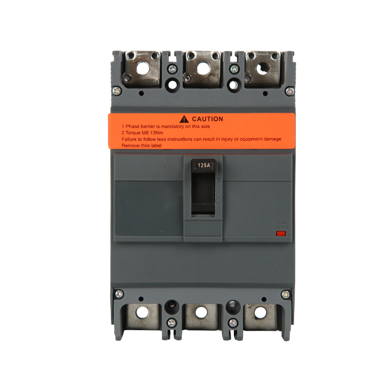
A molded case circuit breaker, commonly abbreviated as MCCB, is an electromechanical protective device housed in an insulated molded plastic casing that automatically interrupts electrical current when it detects an overload or short circuit condition. Unlike a fuse, which must be physically replaced after it blows, an MCCB can be manually reset and reused after tripping, which makes it the preferred protection device in commercial and industrial electrical distribution systems where downtime for replacing blown fuses would be impractical. MCCBs are typically rated for current capacities ranging from around 63 amps up to 6300 amps, placing them well above the smaller miniature circuit breakers used in residential panels and making them suitable for protecting larger feeders, motors, and distribution panels.
Internally, the breaker uses a combination of thermal and magnetic sensing elements to detect abnormal current conditions. A thermal element responds to sustained overload conditions by bending a bimetallic strip as it heats up, eventually triggering the trip mechanism, while a magnetic element responds almost instantly to the much higher current levels associated with short circuits, tripping the breaker within milliseconds to prevent damage to downstream equipment and wiring.
Key Components Inside an MCCB
Understanding the internal components of a molded case circuit breaker helps engineers and maintenance personnel select the right breaker for a given application and diagnose issues when one fails to operate correctly.
Trip Units and Sensing Mechanisms
Most MCCBs use either a thermal-magnetic trip unit or an electronic trip unit, with the choice affecting both cost and the level of protection customization available. Thermal-magnetic units are simpler and more affordable, relying on fixed physical components to determine trip thresholds, which works well for general-purpose applications where adjustable settings are not required. Electronic trip units use current sensors and a microprocessor to monitor current continuously, allowing adjustable settings for long-time pickup, short-time pickup, and instantaneous trip thresholds, which gives engineers far more precise control over how the breaker coordinates with other protective devices in a larger distribution system.
Frame Size and Interrupting Capacity
The frame size of an MCCB refers to its physical housing size category, which correlates with its maximum current rating and determines how much current the breaker’s internal contacts and casing can physically accommodate. Interrupting capacity, often listed as the breaker’s kilo-ampere interrupting rating or kAIC, indicates the maximum fault current the breaker can safely interrupt without the contacts welding shut or the casing failing. Selecting a breaker with an interrupting capacity below the available fault current at its installation point is a serious safety hazard, since the breaker could fail catastrophically rather than safely clearing the fault during a major short circuit event.
MCCB vs MCB: Choosing the Right Breaker Type
Molded case circuit breakers are often confused with miniature circuit breakers, commonly abbreviated as MCBs, but the two serve different roles within an electrical system. MCBs are typically rated up to around 125 amps and are designed for lighter residential and small commercial circuits, while MCCBs handle the higher current loads found in industrial machinery, large commercial panels, and main distribution feeders. MCCBs also generally offer adjustable trip settings on models with electronic trip units, a feature rarely found on standard MCBs, which are usually fixed at a single trip threshold determined during manufacturing.
Another practical difference lies in interrupting capacity, since MCCBs are built to handle significantly higher fault currents than MCBs, making them appropriate for installation closer to the main electrical service where available fault current is typically much higher than at branch circuit locations further downstream.
Comparing Common MCCB Trip Curve Types
| Trip Curve | Typical Trip Multiple | Common Application |
| Type B | 3 to 5 times rated current | Resistive loads, lighting circuits |
| Type C | 5 to 10 times rated current | General industrial and motor loads |
| Type D | 10 to 20 times rated current | Transformers and high inrush motor starts |
Selecting the Right Interrupting Rating for Your Application
Determining the correct interrupting rating requires performing or reviewing a short circuit study for the installation point, which calculates the maximum available fault current based on the upstream transformer size, utility source impedance, and conductor lengths in the system. Engineers then select a breaker whose interrupting rating exceeds this calculated fault current with an appropriate safety margin, since available fault current generally decreases as you move further from the utility source due to the added impedance of conductors and transformers along the path.
It is also important to verify the breaker’s rating under the correct voltage and frequency conditions specified in its datasheet, since interrupting capacity figures are voltage-dependent and a breaker rated for adequate fault clearing at 240 volts may have a different rating entirely at 480 volts or higher system voltages.
Installation Best Practices
Proper installation of an MCCB starts with confirming adequate clearance around the breaker for heat dissipation, since these devices generate heat during normal operation and insufficient airflow can cause premature thermal tripping or accelerated component wear. Torque values on terminal connections should follow the manufacturer’s specified range exactly, since connections that are too loose create resistance heating at the contact point, while connections torqued too tightly can damage the terminal lug or breaker housing.
Breakers should also be installed with consideration for selective coordination with upstream and downstream protective devices, meaning the trip settings are configured so that only the breaker closest to a fault trips, rather than causing a larger upstream breaker to trip unnecessarily and shut down power to unaffected circuits. This coordination study is particularly important in facilities like hospitals or data centers where unplanned, widespread outages carry significant operational risk.
Maintenance and Testing to Ensure Reliable Protection
Routine testing of MCCBs is essential because a breaker that fails to trip during an actual fault condition defeats the entire purpose of having protective devices installed in the first place. Primary current injection testing, performed by qualified electrical testing personnel, verifies that the breaker actually trips at its rated thresholds rather than relying solely on visual inspection or manufacturer specifications. Many facilities schedule this testing on a periodic basis, often every one to three years depending on the criticality of the circuit being protected and any applicable regulatory or insurance requirements.
- Inspect terminal connections periodically for signs of discoloration or corrosion, which can indicate developing resistance heating issues.
- Exercise breakers that remain in a fixed position for long periods by manually opening and closing them to prevent mechanical components from sticking.
- Keep a record of trip events and their causes to identify whether a breaker is tripping due to genuine faults or nuisance tripping from undersized settings.
- Replace breakers that have interrupted a significant short circuit event, since internal contact damage from a major fault may not be visible externally.
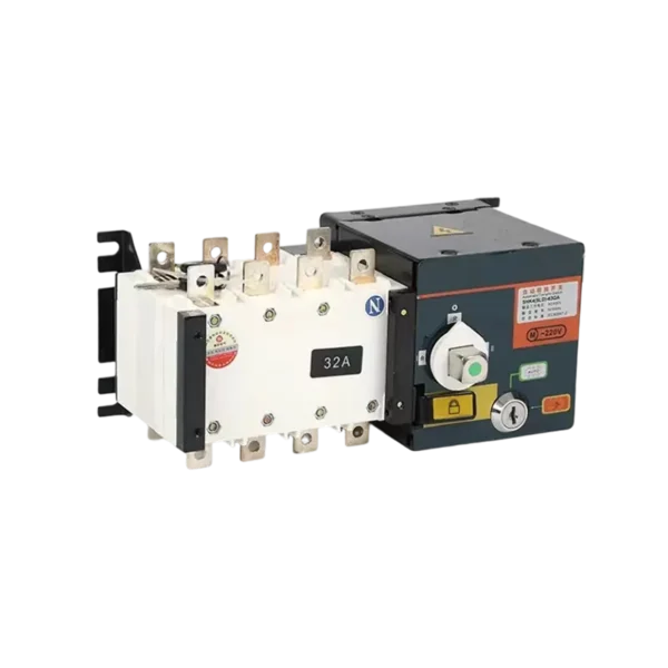
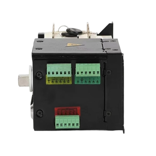
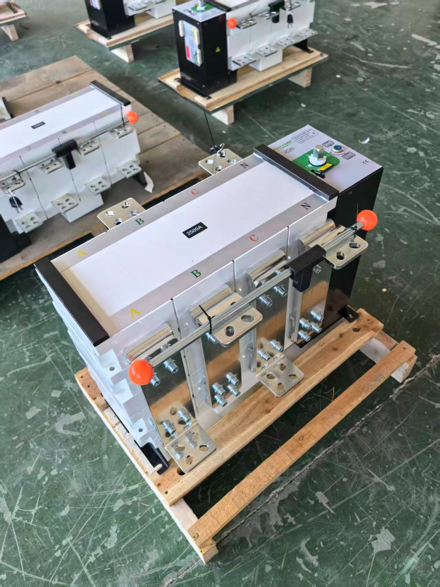
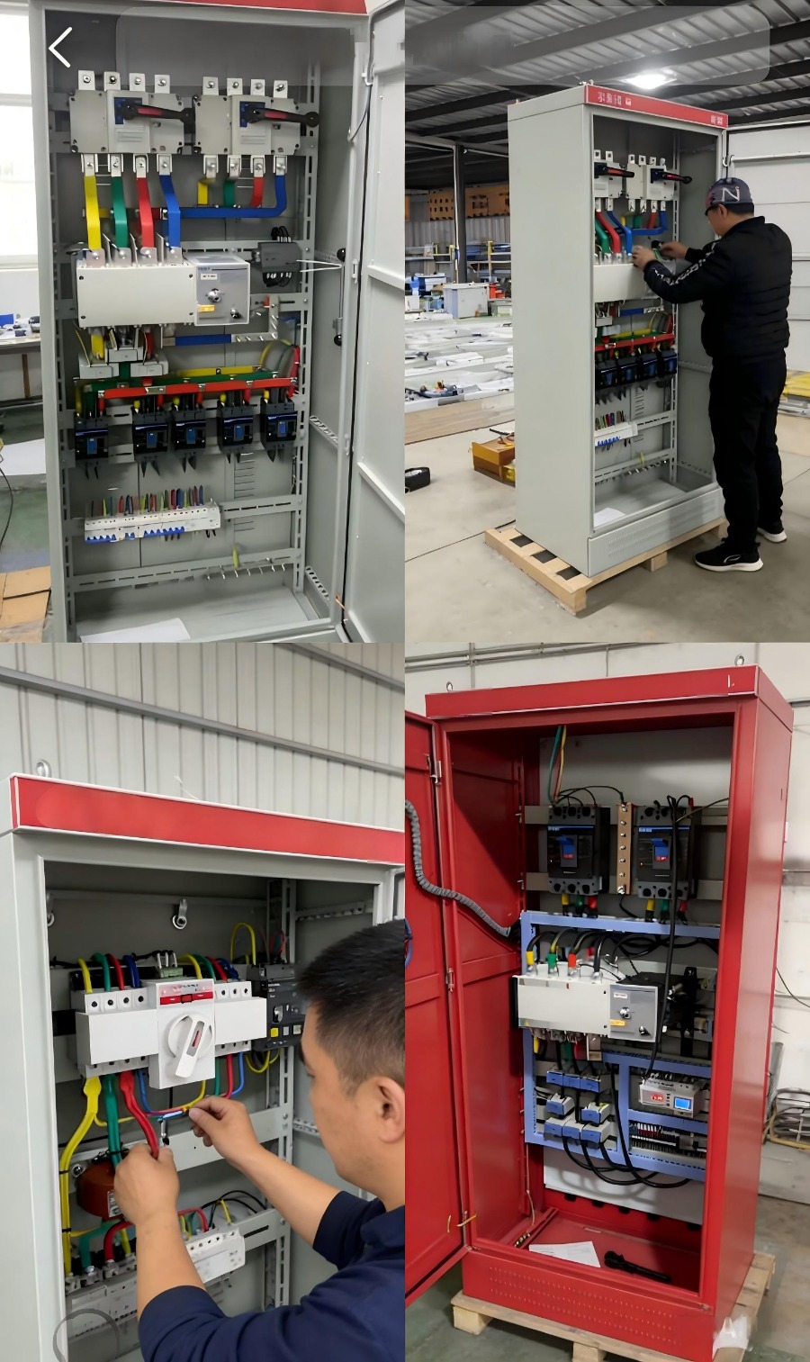
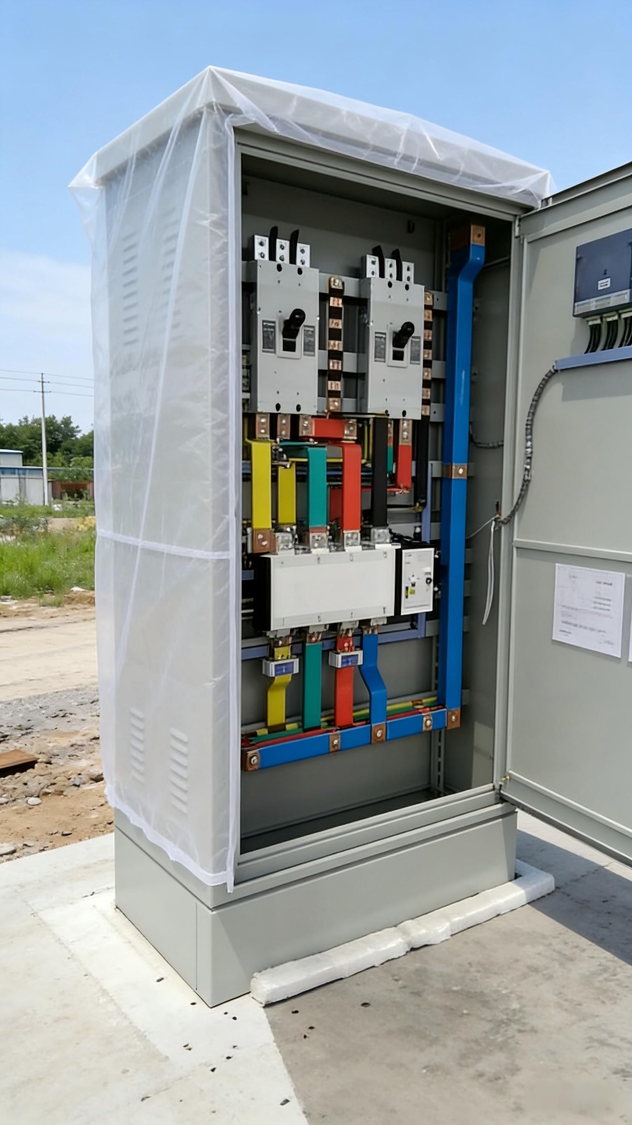
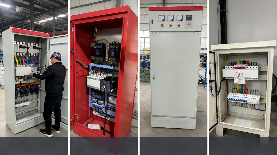
ATS Automatic Transfer Switch 100A–630A – 3P/4P Generator Backup
 |
 |
 |
 |
 |
 |
 |
|
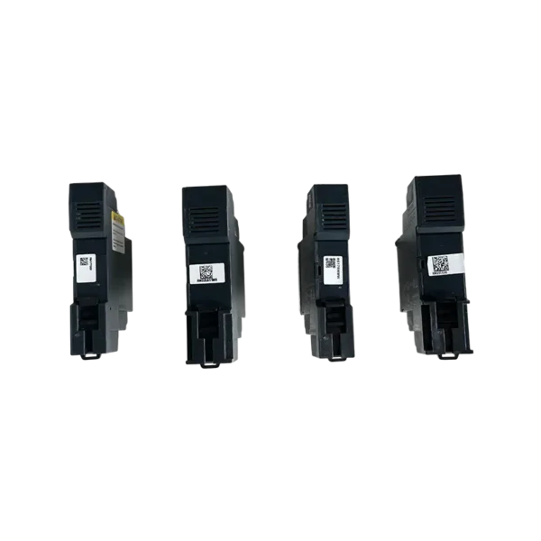
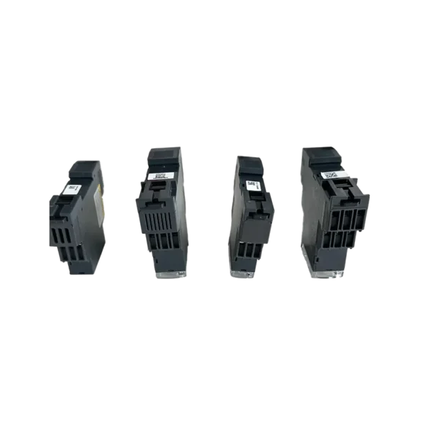
RM22UB34 Single-Phase Voltage Monitoring Relay